Views: 0 Author: Site Editor Publish Time: 2026-06-14 Origin: Site
Modern infrastructure faces a massive engineering challenge today. Facilities must scale power distribution networks to meet surging load demands. They must achieve this without compounding line losses or expanding their physical footprint. Standard low-voltage setups simply cannot keep up. They suffer significant voltage drops over long distances. High-density environments quickly run out of physical space for bulky parallel conduits. Standard low-voltage systems become inefficient under massive continuous loads.
This is where higher capacity systems step in. We define the standard threshold typically between 2kV and 35kV. Transitioning to this tier provides a robust structural solution. You can push more energy through smaller spaces efficiently. Standard solutions fail when distance and density increase simultaneously. This article serves as a technical evaluation guide. Project engineers and procurement teams will learn how to validate this vital network upgrade. You will understand the physics, structural benefits, and compliance requirements needed for a successful transition.
Efficiency at Scale: Medium voltage solutions drastically reduce current flow for the same power output, minimizing thermal losses over long distances.
Spatial Economy: Higher voltage allows for smaller conductor cross-sections, optimizing conduit space in dense environments like data centers and industrial plants.
Total Cost of Ownership (TCO): While termination and installation require specialized labor, the long-term savings in copper/aluminum volume and energy efficiency yield a positive ROI for heavy-load networks.
Compliance & Reliability: Modern insulation (XLPE/EPR) and standardized shielding protocols ensure robust fault tolerance and adherence to global utility standards.
Facility managers quickly notice the symptoms of an overburdened low-voltage system. Identifying the bottleneck early prevents catastrophic infrastructure failure. Excessive voltage drops occur frequently across expansive facility layouts. Equipment overheating becomes a daily operational hazard. Frequent breaker trips disrupt continuous manufacturing processes. Over time, you notice a bloated physical footprint. Facilities run out of available tray space for additional wiring.
You must understand the physics of power transmission to fix this. Voltage and current share an inverse relationship. Higher voltage means lower current for identical power loads. Lower current directly translates to reduced $I^2R$ thermal losses. $I^2R$ represents the energy lost as heat within the conductor. When you reduce the current flow, you exponentially reduce these thermal losses. Copper heating wastes valuable energy. It also prematurely ages the surrounding insulation materials.
We must define what a successful distribution upgrade looks like. Success criteria require stabilized ampacity across the entire network. Your system must achieve strict regulatory compliance. It must also ensure scalability for future load additions. Engineers need headroom to add more machinery or server racks later. A successful upgrade resolves immediate thermal issues while building long-term capacity. It transforms a strained grid into a highly responsive utility framework.
Engineers need a reliable decision framework for upgrading network tiers. Transitioning between voltage levels requires careful capacity planning. We use a capacity versus distance matrix to guide these decisions. Certain thresholds make standard wiring mathematically impractical. When facility runs exceed 1,000 feet, low-tier wiring suffers severe attenuation. Loads surpassing specific megawatt thresholds require specialized conductors. You must evaluate these constraints early in the design phase.
Load Demand | Distance Range | Recommended Voltage Tier | Primary Limiting Factor |
|---|---|---|---|
Below 1 MW | Under 300 feet | Low Voltage (e.g., 480V) | Standard equipment compatibility |
1 MW to 3 MW | 300 to 1,000 feet | Transitional Evaluation | Voltage drop and conduit space |
Above 3 MW | Over 1,000 feet | Medium Voltage (e.g., 15kV) | Thermal losses and conductor bulk |
Material and spatial trade-offs heavily influence the final design layout. Compare the bulk of parallel low-voltage lines against streamlined alternatives. A standard setup might require ten parallel conduits to handle 5MW. This massive bundle consumes valuable subterranean or overhead rack space. Conversely, a single optimized circuit easily carries the same load. The higher voltage tier dramatically shrinks the required conductor cross-section. You save significant physical space within tight structural corridors.
We must also evaluate operational material realities over the asset lifecycle. Transparently comparing upfront material requirements reveals long-term efficiency advantages. High-tier conductors require much less raw copper or aluminum volume. However, they feature significantly higher insulation complexity. Specialized shielding layers add manufacturing intricacy. Over a 20 to 30-year lifecycle, you conserve massive amounts of energy. The efficiency gains easily justify the specialized insulation requirements. Using a reliable Power Cable ensures safe and efficient energy transfer across these specific distance metrics.
Continuous high-load operations demand exceptional thermal stability and ampacity retention. Modern infrastructure cannot afford localized heat degradation. A properly specified Medium Voltage Cable maintains peak performance under extreme continuous loads. The reduced current flow generates significantly less internal heat. This thermal stability prevents degradation of the surrounding infrastructure. Nearby data cables or sensitive equipment remain unaffected by high temperatures. Ampacity ratings remain stable even during peak facility utilization.
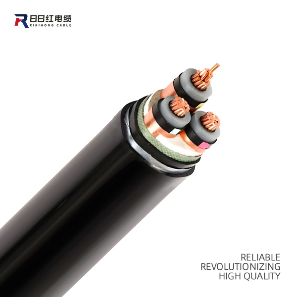
Enhanced fault tolerance represents another critical structural advantage for facility managers. Break down the structural engineering behind concentric neutral shielding. These copper wire shields safely carry fault currents back to the source. They also trigger protective relays instantly during an emergency. Semi-conductive layers play an equally vital role in managing electrical stress. They smooth out the electrical field surrounding the conductor. This prevents localized voltage spikes from piercing the insulation layer. These integrated layers actively prevent localized catastrophic failures.
Grid resilience separates standard setups from highly optimized enterprise networks. Industrial grids experience constant fluctuations and transient overvoltages. Heavy machinery startups cause significant power surges. Lower-tier alternatives often fail or degrade under repetitive electrical stress. High-tier networks better handle these aggressive transient overvoltages. The robust dielectric strength absorbs sudden spikes without insulation breakdown. This resilience ensures uninterrupted power delivery for mission-critical facility operations.
Different industrial sectors leverage these structural advantages to solve unique challenges. Understanding these applications helps engineers validate their own specific use cases.
Data Centers & Hyperscale Facilities: Server floors require massive energy inputs. Addressing this critical need demands compact power routing solutions. Facilities cannot support massive thermal burdens near sensitive cooling zones. High-tier distribution brings power directly to the server floor seamlessly. It utilizes step-down transformers locally to minimize heat generation. Density requirements make this the only viable routing method.
Renewable Energy Integrations: Solar and wind farms span vast geographic areas. They face massive distance-related attenuation challenges daily. Explaining the necessity of this technology requires looking at collector networks. Inverters push power to step-up transformers across the field. High-capacity conductors transport this energy efficiently before grid interconnection. They eliminate crippling power losses over multi-mile infrastructure runs.
Heavy Manufacturing Plants: Steel mills and automotive plants operate enormous mechanical loads. Massive rotating machinery requires huge initial starting currents. Localized substations fed by high-capacity lines solve this problem perfectly. They distribute power deep within large industrial plants efficiently. This isolates heavy equipment noise from the rest of the facility. It ensures stable operation for sensitive automation controls nearby.
Selecting the correct materials guarantees long-term operational success. Insulation chemistry dictates the environmental resilience of the entire circuit. Provide an objective comparison between available polymer formulations. Cross-Linked Polyethylene (XLPE) offers exceptional moisture resistance and overall dielectric strength. Ethylene Propylene Rubber (EPR) provides superior flexibility for complex installations. Project engineers must match the polymer to the installation environment carefully.
Feature | Cross-Linked Polyethylene (XLPE) | Ethylene Propylene Rubber (EPR) |
|---|---|---|
Moisture Resistance | Excellent, highly impermeable | Good, but slightly permeable |
Flexibility | Rigid, requires larger bend radii | Highly flexible, easier to route |
Dielectric Strength | Very high, minimal losses | High, slightly more lossy than XLPE |
Thermal Stability | Strong up to 90°C continuous | Excellent in extreme thermal cycles |
Conductor material choice equally impacts final network performance metrics. Evaluate Copper versus Aluminum based on stringent project-specific constraints. Copper offers unmatched conductivity and smaller physical diameters. It requires less space but carries a heavier weight penalty. Aluminum provides a lightweight alternative for long overhead or tray runs. However, aluminum requires larger diameters to match copper ampacity. Termination requirements differ vastly between the two elemental metals.
Regulatory baselines enforce safety and reliability across global infrastructure projects. List mandatory evaluation lenses before finalizing any procurement decision. Engineers strictly reference IEEE, ICEA, IEC, and VDE international standards. These frameworks dictate shielding thickness, test voltages, and installation safety parameters. Advise buyers to demand certified factory test reports unconditionally. Partial discharge testing proves the insulation contains no microscopic manufacturing voids. Skipping these compliance verifications invites immediate operational liability.
Transitioning to higher tier networks introduces specific field execution challenges. Installation complexities represent the highest risk factor during facility upgrades. Acknowledge the mandatory requirement for certified, highly trained splicers. Do not minimize the risk of poor termination practices. Poor termination remains the leading cause of catastrophic field failure. Improperly stripped semi-conductive layers create localized electrical stress points. These errors eventually burn through the primary insulation jacket.
Space and routing requirements demand precise structural engineering oversight. Note the specific bending radius limitations for these rigid conductors. Bending lines too tightly physically fractures the internal metallic shielding. Trenching and conduit requirements also follow strict spatial guidelines. Direct burial necessitates specific jacket thickness and soil thermal resistivity calculations. Duct banks require proper spacing to dissipate accumulated underground heat efficiently.
Maintenance assumptions dictate the long-term reliability of the distribution network. Outline routine testing requirements necessary to maintain manufacturer warranty status. Predictive maintenance prevents unexpected outages.
VLF (Very Low Frequency) Testing: Applies a low-frequency AC voltage to verify insulation integrity without damaging the polymer structure.
Tan Delta Testing: Measures the dielectric dissipation factor to identify water treeing or insulation aging before failure occurs.
Infrared Thermography: Scans terminations and splices under peak load to detect abnormal heating patterns caused by loose connections.
Provide logical next-step actions for project teams. We recommend initiating a comprehensive load-flow study first. This identifies precise capacity requirements and future expansion headroom. Schedule a technical consultation with specialized structural engineers. They will verify conduit pathways and underground tray capacities. Finalize these structural evaluations before issuing any procurement orders.
Transitioning to a higher capacity distribution tier represents a strategic structural decision. It goes far beyond a simple material substitution process. Resolving thermal bottlenecks requires advanced physics and specialized infrastructure planning. These robust systems drastically reduce spatial footprints in dense operational environments.
Emphasize the long-term operational stability gained from this vital transition. Upfront engineering and specialized installation demands remain undeniably rigorous. However, the operational stability and drastically reduced line losses prove invaluable. It remains the only viable choice for scaling massive industrial networks. You cannot support modern megawatt demands using outdated low-tier architecture.
Take immediate action to secure your facility infrastructure. Prompt your team to review project specifications with an engineering consultant today. Map out your load demands and calculate distance-related attenuation carefully. Request customized technical data sheets from a certified manufacturer to verify compliance constraints.
A: The industry universally defines this range as operating between 2kV up to 35kV. This tier bridges the gap between low-voltage local distribution (under 1kV) and high-voltage long-distance transmission networks (typically 69kV and above). It serves perfectly for regional utility distribution and large internal facility networks.
A: Shielding serves three critical functions. It contains the electrical field uniformly within the insulation, preventing localized stress. It ensures personnel safety by providing a solid ground path for fault currents. Finally, it prevents atmospheric ionization, which stops ozone degradation from destroying the protective outer jacket over time.
A: Yes, they can be directly buried if properly constructed. Direct burial requires specialized heavy-duty outer jackets to resist moisture and soil chemicals. Metallic armoring provides necessary protection against physical crush damage and rodents. Always consult local electrical codes to determine depth and backfill material stipulations.
A: A properly engineered network typically lasts between 30 and 40 years. This lifespan remains highly contingent on perfect field terminations and splice executions. Environmental factors, continuous heat exposure, and routine predictive maintenance also directly influence the overall longevity of the installed polymer insulation.