Views: 0 Author: Site Editor Publish Time: 2026-11-05 Origin: Site
Power grid failures cost industries billions every single year. Selecting the incorrect conductor can trigger catastrophic safety hazards alongside crippling operational downtime. Picture a sprawling manufacturing plant suddenly going dark. Why does this happen? Often, an underspecified underground line ruptures under intense thermal stress. I have seen this happen in the field too many times. To prevent such disasters, engineers must match electrical infrastructure to exact load requirements.
In this comprehensive guide, we explore the critical distinctions between high and medium-tier power networks. By understanding these structural and operational specifications, field contractors and procurement managers can ensure long-term grid stability.
Voltage Thresholds: Intermediate networks typically manage electrical loads between 5kV and 35kV. In contrast, high-capacity infrastructure is engineered for macro-level transmission, operating from 69kV up to 345kV and beyond.
Structural Variances: Transmission lines require exceptionally thick insulation and advanced shielding mechanisms to prevent electrical breakdown. A lower-tier alternative provides a practical balance between robust dielectric strength and manageable physical flexibility.
Application Differences: Massive transmission systems are exclusively utilized for long-distance power transport, connecting generation plants to main substations. Localized networks handle regional distribution, moving power from substations directly to industrial facilities or commercial grids.
Cost and Installation: Over-specifying a transmission-grade line for a localized distribution project drastically inflates material costs. It also demands specialized jointing labor and needlessly complicates the routing process.
Understanding the precise definition of distribution-level infrastructure is the foundational step in designing a safe electrical network. These conductors bridge the critical gap between massive transmission lines and the low-voltage wiring utilized inside commercial buildings.
In electrical engineering, voltage classifications help standardize equipment and guarantee operational safety. The universally accepted range for these intermediate applications typically spans from 5kV up to 35kV. However, specific international standards defined by the International Electrotechnical Commission and the Institute of Electrical and Electronics Engineers may present slight regional variations in these exact thresholds.
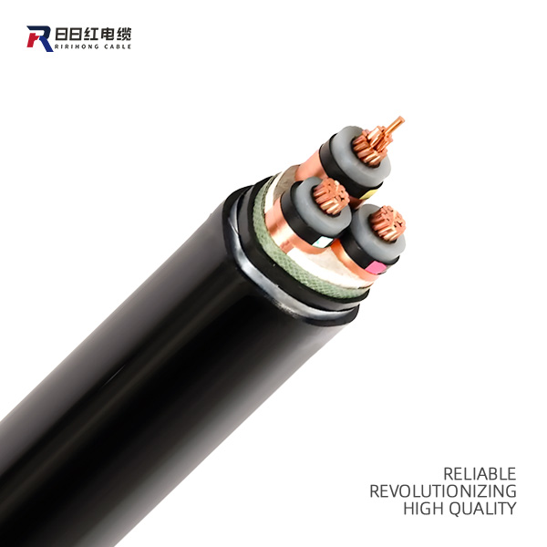
The fundamental role of a reliable Med Voltage Cable is to facilitate the safe step-down of power. When electricity arrives at a regional utility substation from a high-capacity transmission line, transformers reduce the intense voltage. The intermediate network then carries this localized power through city duct banks, underground trenches, and industrial parks without introducing the extreme risks associated with raw transmission loads.
Because of their balanced capacity for power delivery and physical routing flexibility, these conductors form the backbone of modern commercial infrastructure. Primary use cases include:
Renewable Energy Grids: Connecting individual turbines in wind farms or solar panel arrays to central collection substations.
Heavy Industrial Plants: Powering large-scale manufacturing machinery, arc furnaces, and automated assembly lines.
Mining Operations: Providing durable power distribution in harsh subterranean environments where mechanical toughness is mandatory.
Large Commercial Complexes: Supplying electricity to hospital campuses, university networks, and sprawling shopping centers.
Railway Systems: Distributing traction power along transit corridors for light rail and heavy commuter trains.
To accurately evaluate distribution options, we must establish a clear baseline for high-capacity infrastructure. These lines are highly specialized components. They operate on entirely different parameters than their intermediate counterparts.
Engineered to handle extreme electrical stress, the standard range for these lines begins at 69kV and extends up to 345kV. For massive continental power grids, infrastructure can even push into the Ultra-High classification, which manages staggering loads of 500kV and above.
The necessity of this extreme capacity lies in the physics of power transmission. When electricity travels over vast geographic distances, it experiences resistance. This leads to energy loss in the form of heat. By drastically increasing the voltage, utility companies can proportionally decrease the current. Lower current significantly minimizes these energy losses. Consequently, this makes it the only economically and physically viable method for transporting electricity across hundreds of miles.
Rarely seen by the average consumer, these massive conductors are deployed exclusively in macro-level infrastructure projects. Their primary applications include forming the main arteries of national power grids. They link massive nuclear or hydroelectric generation plants to the primary grid and establish subsea transmission links that connect offshore mega-farms to the mainland.
For project engineers and procurement managers, understanding the physical and chemical construction of these materials is crucial. The internal architecture of a conductor dictates its performance, longevity, and suitability for specific routing environments.
Feature | Medium Voltage | High Voltage |
|---|---|---|
Voltage Range | 5kV to 35kV | 69kV to 345kV+ |
Insulation Thickness | Moderate, balances strength and flexibility | Exceptionally thick, requires clean-room purity |
Shielding Complexity | Standard copper tape or wire screens | Advanced geometric grading and heavy metallic sheaths |
Physical Footprint | Manageable for standard trenching and duct banks | Extremely stiff and heavy, requires motorized winches |
Primary Application | Localized distribution and industrial facilities | Long-distance national grid transmission |
The insulation layer acts as the primary defense against catastrophic electrical faults. Distribution-level networks predominantly utilize Cross-linked Polyethylene or Ethylene Propylene Rubber. Cross-linked Polyethylene provides excellent moisture resistance and thermal stability, making it ideal for standard utility routing. Ethylene Propylene Rubber is slightly more pliable, offering superior performance in highly flexible applications such as mining equipment.
Furthermore, transmission lines also rely on Cross-linked Polyethylene, but the polymer undergoes a much more rigorous manufacturing process. They require highly purified, extra-thick insulation to manage intense electrical stress. Any microscopic impurity or void in the insulation of a 138kV line can trigger partial discharge. This localized electrical breakdown eventually destroys the entire circuit. Consequently, the insulation wall on a high-capacity line is significantly thicker and manufactured in highly controlled clean-room environments.
As voltage increases, the electric field surrounding the copper or aluminum core becomes increasingly volatile. Both tiers utilize semi-conductive screens and metallic shields. These layers confine the electric field within the insulation and provide a safe path for fault currents to reach the ground.
From a structural standpoint, transmission systems require far more complex stress-control mechanisms. The metallic sheathing is often heavier, utilizing corrugated aluminum or thick copper wire screens to manage massive fault currents. The transition points and terminations require intricate geometric grading to prevent the electric field from concentrating and tearing through the polymer. A standard distribution line still requires precise shielding, but the lower electrical stress allows for less bulky screen designs and simpler termination procedures.
Thicker insulation and heavier shielding create a drastically different physical footprint. High-capacity lines are incredibly stiff, dense, and heavy. They require specialized heavy-duty routing, massive wooden drums, and highly orchestrated pulling operations using motorized winches. The bend radius is vast, meaning they cannot navigate tight corners inside a facility.
In contrast, intermediate options offer substantially more flexibility. While still robust and heavy compared to residential wiring, their smaller overall diameter makes them far more manageable. Contracting crews can effectively handle standard trenching, pull them through municipal conduit systems, and route them inside industrial switchgear rooms.
For field engineers, electrical contractors, and site inspectors, rapidly identifying materials in a muddy trench is a fundamental safety requirement. Misidentifying a live line leads to improper handling, inadequate safety clearances, and fatal accidents.
The most reliable method for immediate on-site identification is examining the printed outer jacket markings. Standardized by global regulatory organizations, these stamps provide a comprehensive profile of the conductor specifications.
When inspecting the jacket, look for the voltage rating explicitly printed along the length of the sheath. A distribution line will typically display ratings such as 5kV, 15kV, 25kV, or 35kV. In contrast, transmission lines will indicate ratings from 69kV upwards. Additionally, the markings will detail the cross-sectional area, the core material, and the specific standard codes the product adheres to. Checking these printed codes is the crucial first step before any physical manipulation begins.
If the markings are obscured by dirt or if you are inspecting a cutaway section, structural cues become invaluable. A transmission-grade line will have a visibly disproportionate insulation layer relative to the central conductor size. The metallic sheathing will also feel substantially heavier and more rigid.
Flexibility serves as another immediate indicator. If a line requires specialized hydraulic equipment and massive turning radii just to be positioned in a trench, it is likely a high-capacity transmission line. Distribution lines, while still requiring effort, can generally be manipulated, bent, and pulled through standard utility vaults by conventional contracting crews.
The electrical manufacturing sector is evolving rapidly to meet the demands of modern smart grids and stringent environmental regulations. Industry analysts tracking the global energy transition highlight a massive paradigm shift. The surging deployment of decentralized renewable energy, such as offshore wind and localized solar farms, is fundamentally reshaping distribution network demands. Grid modernization now relies heavily on upgrading aging infrastructure to handle bidirectional power flows. As a result, intermediate voltage networks sit at the absolute center of this technological revolution.
Specifically, advancements in polymer technology have introduced Tree-Retardant Cross-Linked Polyethylene. Water treeing is a phenomenon where microscopic moisture impurities cause branching degradation within the insulation over time. This eventually leads to electrical breakdown. The new tree-retardant materials actively inhibit the formation of these structures, drastically extending the operational lifespan of underground circuits.
Beyond material chemistry, the integration of smart monitoring technology transforms passive conduits into active grid sensors. Modern manufacturing processes allow continuous fiber optic strands to be embedded directly within the metallic shield layer. These integrated fibers enable distributed temperature sensing and real-time partial discharge monitoring. By continuously analyzing the thermal profile along the entire run, operators transition from reactive repairs to predictive maintenance. They can identify localized hotspots weeks before a physical failure occurs.
Selecting the correct electrical infrastructure is a complex decision matrix that impacts the total lifecycle of a power network. Over-specifying drains project budgets. Under-specifying introduces severe safety hazards and grid instability.
The primary factors dictating your selection are the anticipated electrical load and the geographic distance of the run. Electrical engineers calculate the required ampacity and acceptable voltage drop over the specified distance.
For localized power delivery, such as stepping down power from a main utility substation to an industrial plant two miles away, specific parameters are required. A standard 15kV rated conductor featuring a 133 percent insulation level and a robust copper tape shield is often the optimal engineering choice. Specifying a high-performance Med Voltage Cable ensures highly efficient power delivery without the extreme infrastructure costs associated with transmission systems. Conversely, if the project involves connecting a newly constructed offshore wind farm to a mainland grid fifty miles away, the power loss over that distance at lower voltages is unacceptable. That scenario inherently requires a high-capacity solution.
The installation environment severely impacts the choice of outer jacketing, armoring, and moisture protection mechanisms.
When routing underground via direct burial, the line is subjected to soil moisture, mechanical stress from ground movement, and potential rodent damage. In these scenarios, engineers specify robust steel wire armor or corrugated aluminum tape to provide mechanical crush resistance. Additionally, water-blocking tapes or swellable powders are integrated beneath the outer sheath to prevent longitudinal water ingress. High-density polyethylene jackets are frequently chosen for underground duct banks due to their superior abrasion resistance.
For overhead installations or routing through controlled indoor trays, heavy armoring may not be necessary. Instead, the focus shifts to UV resistance, flame retardancy, and low-smoke zero-halogen properties to ensure personnel safety in enclosed commercial environments.
Procurement managers must evaluate the Total Cost of Ownership, which extends far beyond the initial material purchase price per meter. Transmission infrastructure is exponentially more expensive. The materials require ultra-pure manufacturing environments, and installing them demands elite specialized jointers working in heavily controlled conditions.
Choosing a properly specified distribution solution optimizes the return on investment. The material costs are lower, installation labor is more widely available, and standard splicing kits can be utilized. Over-engineering a system provides no tangible performance benefits to a localized grid.
Identifying the right technical specifications is only half the battle. Procuring the materials from a reputable manufacturer is equally critical. The integrity of a power distribution network is entirely dependent on the manufacturing quality of its foundational components.
The dangers of subpar manufacturing in power distribution cannot be overstated. A product extruded with poor temperature controls or impure insulation materials is a ticking time bomb. Micro-voids or dust particles in the polymer matrix create localized areas of high electrical stress. These imperfections inevitably lead to partial discharge, causing premature failure, localized fires, and massive network downtime.
To mitigate these risks, procurement teams must demand rigorous documentation of Factory Acceptance Testing. Reliable manufacturers subject every batch to stringent testing protocols. This includes Very Low Frequency testing, partial discharge measurements, and dielectric withstand tests. This ensures absolute compliance with international regulatory standards.
Selecting the right manufacturing partner guarantees that your electrical network will operate safely and efficiently for decades. Industry leaders invest heavily in state-of-the-art triple extrusion lines, clean-room material handling, and advanced quality control laboratories.
When planning your next commercial, industrial, or renewable energy distribution project, it is essential to source materials from established entities with a proven track record. For engineers and procurement teams seeking dependable infrastructure, explore the comprehensive catalog of certified Med Voltage Cable solutions at RRH Cable. We provide rigorously tested products designed to meet the exact tolerances required for safe, long-term operation under the most demanding environmental conditions. Contact our engineering team today to match the perfect conductor to your specific project needs.
In standard electrical engineering practices, this tier is defined as handling electrical loads between 5kV and 35kV. It is important to note that specific regional standards may slightly alter these classifications. Regardless of minor regional variations, these conductors serve the primary function of localized power distribution.
Technically, a transmission-grade line is capable of carrying a lower voltage load, as its insulation and shielding are heavily over-engineered. However, doing so is highly impractical and strongly discouraged by engineering professionals. The infrastructure is exponentially more expensive, drastically inflating project costs. Furthermore, their extreme weight and rigid bend radius make routing through standard commercial trenches unnecessarily difficult and labor-intensive.
Electrical infrastructure is categorized into three primary tiers based on capacity and intended application. Low voltage handles up to 1kV and is utilized for residential wiring and standard appliance power. The intermediate tier ranges from 5kV to 35kV and is engineered for localized distribution, connecting utility substations to industrial plants. High capacity operates from 69kV up to 345kV and is exclusively designed for long-distance power transmission across national utility grids.
The minimum bending radius is a critical specification during installation to prevent mechanical damage to the insulation and shielding. For standard unarmored lines, the bending radius is typically 12 times the overall outer diameter. For armored lines, which are stiffer, it generally increases to 15 times the overall diameter. Exceeding this limit during a tough pull through a utility vault can cause microscopic tears in the shielding, leading to premature failure.
Before bringing a newly installed circuit online, field engineers must perform a series of rigorous safety tests. The most common procedures include Very Low Frequency testing, which applies an AC voltage at a fraction of a Hertz to stress-test the insulation without damaging it. Engineers also perform insulation resistance testing using a megohmmeter to check for immediate shorts, and partial discharge testing to identify any microscopic voids or installation damage in the splices and terminations.
When engineered with high-quality insulation materials and installed strictly according to manufacturer and regulatory guidelines, these networks boast a highly reliable operational lifespan. On average, they are designed to last between 30 to 40 years, and often much longer. Actual longevity depends heavily on external environmental factors, proper moisture protection in underground installations, and operating strictly within the specified thermal limits.
At voltages of 5kV and above, the electrical field surrounding the core becomes intense enough to ionize surrounding air. This leads to corona discharge and rapid insulation degradation. Shielding, which typically consists of a semi-conductive layer combined with a metallic screen like copper tape, is absolutely critical. It confines the electric field entirely within the insulation layer. This ensures uniform electrical stress distribution, prevents dangerous localized discharges, and provides a safe path for fault currents to return to the ground.