Views: 0 Author: Site Editor Publish Time: 2026-09-08 Origin: Site
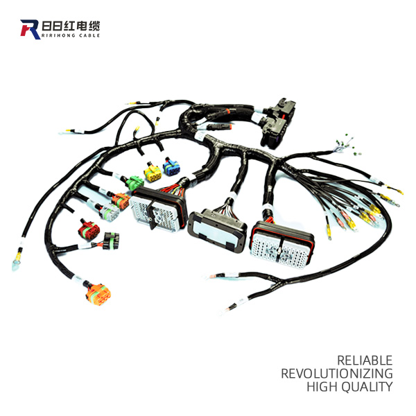
Acting as the central nervous system for complex equipment, a Wiring Harness reliably transmits electrical power and data signals across diverse operational environments. Electrical system failures frequently trace back to these physical interconnects rather than core processors or power supplies. The reliability of any device hinges directly on the structural and electrical integrity of its internal wiring. Specifying these assemblies requires balancing electrical load requirements, environmental stressors like vibration or heat, and manufacturing scalability. Incorrect component selection inevitably leads to signal degradation, field failures, and costly recalls. Evaluating these systems requires a granular understanding of individual electrical components. This guide breaks down the core elements—from conductors and integrated circuit protection to protective shielding. We provide the evaluation criteria necessary for specifying a reliable, compliant assembly tailored to your specific operational environment.
Wires and cables form the foundational backbone of any electrical assembly. A wire consists of a single conductor. A cable contains multiple insulated conductors bundled together within a common jacket. You rely on these conductive pathways to move power from sources to loads. They also transmit low-voltage data signals between sensors and control units. Selecting the right conductor material and physical structure dictates the electrical performance of the entire system. You must evaluate the conductive core based on ampacity requirements, flexibility, and environmental exposure.
Engineers primarily choose between copper and aluminum for the conductive core. Each metal presents distinct physical and electrical characteristics that dictate its field application.
The physical construction of the conductor directly impacts its flexibility and fatigue resistance. You must match the stranding type to the mechanical demands of the installation.
| AWG Size | Typical Stranding | Max Ampacity (Chassis) | Common Field Application |
|---|---|---|---|
| 18 AWG | 16 / 30 | 16 Amps | Low-voltage sensors, LED lighting circuits, data lines. |
| 14 AWG | 41 / 30 | 32 Amps | Standard power distribution, small motors, actuators. |
| 10 AWG | 105 / 30 | 55 Amps | High-draw solenoids, main relay power feeds, alternators. |
| 4 AWG | 133 / 25 | 135 Amps | Battery cables, heavy industrial motor drives, winches. |
Terminals terminate the end of a wire to allow connection to a component or stud. Common types include ring, spade, hook, and quick-disconnect terminals. Ring terminals provide the most secure connection because you must completely remove the mounting screw to detach them. Spade terminals allow for faster assembly and disassembly. Quick-disconnects slide together using friction and are common in relay blocks and switchgear.
Crimp quality represents a massive implementation risk. A proper crimp is a cold weld. The applicator tooling must compress the terminal barrel and copper strands so tightly that all microscopic voids disappear. Over-crimping crushes the copper strands, reducing the cross-sectional area and causing wire damage. Under-crimping leaves microscopic gaps. These gaps allow oxidation, increase electrical resistance, and eventually cause arcing. We verify crimp integrity on the shop floor by cutting the terminal in half, polishing it, and inspecting the cross-section under a microscope.
Connectors house multiple terminals, allowing you to join or separate entire bundles of wires simultaneously. You must evaluate several physical characteristics when selecting connector housings.
| IP Rating | Solid Protection | Liquid Protection | Typical Harness Environment |
|---|---|---|---|
| IP20 | Fingers/Large objects | None | Interior control cabinets, climate-controlled server racks. |
| IP65 | Dust-tight | Low-pressure water jets | Exterior machinery exposed to rain, standard automotive bays. |
| IP67 | Dust-tight | Temporary submersion (1m) | Off-road vehicle chassis, marine applications, heavy construction gear. |
| IP69K | Dust-tight | High-pressure, high-temp washdown | Food processing equipment, medical sterilization devices. |
Splices join two or more wires together within the body of the harness. You can execute splices using mechanical methods or welding. Mechanical splices include butt connectors and crimp caps. They require precise crimping tools and pull-testing to verify mechanical strength. You must cover mechanical splices with adhesive-lined heat shrink to prevent moisture ingress.
Ultrasonic welding uses high-frequency acoustic vibrations to create a solid-state weld between copper strands. Ultrasonic welding eliminates the need for extra metal crimps. It provides superior electrical resistance properties and exceptional mechanical pull-strength. We specify ultrasonic welding for high-current junctions where voltage drop must remain absolute zero.
A reliable electrical system must protect itself and downstream components from overcurrent conditions. Integrating inline overcurrent protection prevents catastrophic thermal events and wire melting during short circuits. You must size the fuse to blow before the wire exceeds its thermal rating.
Blade fuses are the most common automotive and industrial standard. They are easy to inspect and replace. Mini fuses handle low-current sensor circuits, while maxi fuses protect heavy power feeds. For complex systems, engineers integrate centralized power distribution blocks directly into the harness. Fusible links act as a last line of defense. They are short pieces of wire designed to melt and open the circuit before the main harness sustains damage. You typically install fusible links directly at the battery or primary power source.
Relays allow low-current control signals to switch high-current power loads. Placing relays directly within the harness architecture reduces the length of heavy-gauge power wires. You run thick wires only from the power source to the relay, and then to the load. You run thin, lightweight wires from the control switch to the relay coil. This saves weight, reduces voltage drop, and simplifies routing. Contactors perform the same function but handle significantly higher voltage and current levels, typically for large motors or industrial heaters.
Active electronic components embedded in the harness solve specific electrical problems at the hardware level. You utilize inline diodes for reverse polarity protection. They ensure current only flows in one direction, protecting sensitive control modules if someone hooks up a power supply backward. Diodes also provide flyback voltage suppression. When you turn off an inductive load like a starter solenoid, the collapsing magnetic field generates a massive voltage spike. A flyback diode safely dissipates this energy. Resistors drop voltage levels or terminate data lines to prevent signal reflection in CAN bus networks.
The primary insulation extruded directly over the conductor prevents short circuits. You must match the insulation material to the thermal and chemical realities of the operating environment. Dielectric strength and voltage rating requirements dictate the thickness of this insulation. Using standard PVC in an engine bay guarantees premature failure as the jacket hardens, cracks, and exposes the bare copper.
| Insulation Material | Temperature Range | Key Characteristics | Common Applications |
|---|---|---|---|
| PVC (Polyvinyl Chloride) | -40°C to +105°C | Cost-effective, good abrasion resistance, standard flexibility. | General electronics, interior automotive, consumer appliances. |
| Cross-Linked PE (TXL/GXL) | -40°C to +125°C | Resists melting under heat, excellent fluid resistance. | Engine compartments, industrial machinery power routing. |
| PTFE (Teflon) | -90°C to +260°C | Exceptional heat resistance, highly chemical resistant, low friction. | Aerospace, high-temp engine bays, chemical processing equipment. |
| Silicone | -60°C to +200°C | Extreme flexibility, excellent thermal tolerance, poor abrasion resistance. | Medical devices, robotics, tight-bend routing environments. |
Electromagnetic Interference (EMI) and Radio Frequency Interference (RFI) corrupt low-voltage data signals. Shielding is an absolute necessity in data-heavy or mixed-signal harnesses. You must isolate sensitive sensor wires from high-current power wires.
The outer layer of the assembly defends against physical damage. You evaluate coverings based on abrasion resistance, fluid protection criteria, and thermal deflection. Corrugated loom provides excellent crush resistance. Split loom allows for easy installation over completed bundles, while non-split loom offers better fluid protection. Heat shrink tubing creates a tight, rigid seal that prevents moisture ingress, especially when lined with hot-melt adhesive. Expandable braided sleeving allows for extreme flexibility and prevents wires from snagging on sharp metal edges during installation.
A harness must maintain a structured grouping to fit cleanly into the final product. Manufacturers use several techniques to bind wires together. PVC tape provides basic grouping and moisture resistance. PET fleece tape absorbs sound and prevents rattling against metal panels in automotive cabins. Lacing cord, used heavily in aerospace applications, provides a highly secure, low-profile binding method that does not degrade over time like tape adhesives. High-volume manufacturing utilizes automated machines to apply zip ties or tape at precise intervals, ensuring consistent flexibility and shape.
Mechanical stress must never transfer to fragile terminal crimps or splices. Pulling forces will easily rip a wire out of its connector. Strain relief mechanisms absorb these forces. Cable ties anchor bundles to connector housings. Backshells attach to the rear of connectors, enclosing the wire entry points and clamping down on the outer cable jacket. This transfers all pulling force to the rugged outer jacket rather than the internal copper strands.
You must design the assembly to navigate the physical constraints of the equipment enclosure. Designing for bend radius limitations prevents internal conductor breakage. Forcing a thick cable into a sharp 90-degree corner will snap the internal copper strands over time. Mounting hardware dictates how the harness attaches to the chassis. Push-mount ties snap directly into pre-drilled holes. P-clamps secure heavy bundles to flat surfaces using screws, preventing the harness from sagging into moving parts or hot exhaust components.
Specific component choices directly impact the Mean Time Between Failures (MTBF) of the end product. Using a gold-plated terminal instead of a tin-plated one prevents fretting corrosion in low-voltage sensor circuits. Selecting a chemically cross-linked insulation prevents the wire jacket from melting if it accidentally touches a hot manifold. You must map every component feature to a specific reliability outcome in the field. A high-quality wire paired with a cheap, unsealed connector will still result in a system failure when exposed to moisture.
Adhering to industry standards guarantees a baseline of quality and safety. IPC/WHMA-A-620 defines the requirements and acceptance criteria for cable and wire harness assemblies. It provides exact visual standards for acceptable crimps, solders, and routing. You must specify whether your assembly requires Class 1 (general electronic products), Class 2 (dedicated service products), or Class 3 (high performance/harsh environment products). UL certification ensures the materials meet strict fire safety and electrical breakdown standards. RoHS compliance verifies that the components do not contain hazardous materials like lead or mercury.
When engineering a Wiring Harness, you must evaluate the scalability of your component choices. Specifying proprietary connectors locks you into a single supplier. This creates massive supply chain bottlenecks if that supplier experiences production delays. Utilizing standardized, multi-sourced components allows your manufacturing partner to pivot between different brands without altering the core design. This flexibility ensures continuous production scaling without requiring complete engineering redesigns.
Engineers frequently struggle with finding the correct specification balance. Over-specifying involves demanding mil-spec components, extreme temperature ratings, and heavy shielding for benign, indoor environments. This creates unnecessary cost bloat and makes the harness rigid and difficult to install. Under-specifying creates catastrophic risks. Using commercial-grade plastics in high-heat industrial applications guarantees premature failure. You must match the specification strictly to the verified environmental data.
Lead times for specialized electrical connectors can stretch to several months. You mitigate lead-time risks by designing with cross-referenced, equivalent components early in the engineering phase. Establishing form, fit, and function replacements ensures production continues even if the primary component becomes unavailable. Document these approved alternates directly on the engineering drawings to give your procurement team flexibility.
A harness that looks perfect on a CAD screen might be impossible to build efficiently. You must engage with a manufacturing partner early in the design phase. DFM ensures the specified components can be processed on automated equipment. Automated cutting, stripping, splicing, and crimping machines require specific tolerances. If you specify a wire with an unusually sticky insulation, the automated strippers might jam. Good DFM prevents these manufacturing hurdles, ensuring high quality and consistent output.
A: A wire harness groups multiple individual wires together, typically bound by tape or loom, to route them efficiently through a system. A cable assembly features multiple conductors encased within a single, extruded outer jacket. Harnesses offer more flexibility for breaking out wires at different points, while cable assemblies provide superior environmental protection against moisture and abrasion.
A: You select the AWG based on the maximum continuous current the circuit carries and the total length of the wire run. Higher current demands a lower AWG number to prevent overheating. You must also calculate the acceptable voltage drop over the wire's length and factor in the ambient operating temperature of the installation environment.
A: Yes. Integrating active components directly into the harness architecture isolates faults and simplifies routing. Inline fuses provide localized overcurrent protection. Relays allow low-current switches to control high-current loads safely without routing heavy-gauge wire to the switch. Diodes prevent reverse polarity damage and suppress voltage spikes from inductive loads.
A: The most frequent causes are improper terminal crimping, inadequate strain relief, and environmental mismatch. Poor crimps cause high electrical resistance and arcing. A lack of strain relief allows vibration to pull wires out of their connector housings. Using standard insulation in high-heat or chemical environments leads to rapid jacket degradation and short circuits.
A: EMI shielding prevents external electromagnetic noise from corrupting low-voltage data signals. It also stops high-current power wires within the harness from broadcasting interference to nearby sensitive electronics. Shielding is mandatory in systems containing microprocessors, sensors, or communication networks where signal integrity dictates equipment performance.
A: IPC/WHMA-A-620 is the industry consensus standard for the requirements and acceptance of cable and wire harness assemblies. Certification means the manufacturer follows strict, standardized procedures for cutting, stripping, crimping, soldering, and testing. It guarantees consistent, reliable manufacturing quality and provides measurable criteria for accepting or rejecting an assembly.