Views: 0 Author: Site Editor Publish Time: 2026-06-17 Origin: Site
Specifying the wrong sensor connection leads to routing nightmares, signal degradation, or premature field failures. Engineers face this dilemma constantly. A mismatched cable choice quickly turns a simple design into a massive headache on the factory floor. You must carefully distinguish between initial prototyping needs and full-scale production requirements. Standard off-the-shelf cables often suffice when you build early iterations. However, standardized routing becomes absolutely critical once you scale manufacturing lines.
Choosing between standard cables and custom harness assemblies represents a crucial calculation. You must weigh direct labor costs against environmental risks. System lifecycle requirements also strongly dictate this choice. We will explore how to make this critical design decision effectively. You will learn the exact thresholds for pivoting from simple wires to highly engineered solutions. This guide provides actionable frameworks to optimize your next system deployment.
Standard cables offer lower upfront costs and immediate availability, best suited for static, low-complexity, or single-sensor environments.
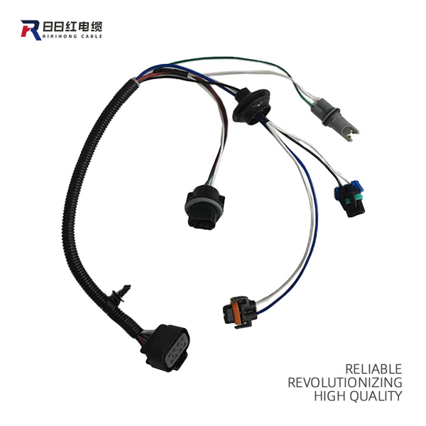
A sensor connection wiring harness reduces OEM assembly time, mitigates vibration/routing failures, and consolidates multiple connections into a single drop-in unit.
The decision threshold relies on analyzing NRE (Non-Recurring Engineering) costs versus long-term savings in installation labor and warranty claims.
Evaluating a wiring loom requires strict attention to AWG sizing, shielding requirements, and supplier testing protocols (e.g., continuity and pull-force testing).
Engineers often use the terms "cable" and "harness" interchangeably. This creates significant confusion during procurement. They represent two fundamentally different approaches to electrical routing. You must understand their architectural differences to specify the right component.
Standard Cables (Jacketed Assemblies): We define standard cables as multiple conductors encased in a single, continuous extruded jacket. Manufacturers typically use PVC, polyurethane, or Teflon for this outer layer. The extrusion process firmly binds the internal wires together.
Limitation: This design offers excellent overall protection against the elements. However, it severely lacks flexibility. You cannot easily create multi-directional breakouts. Integrating application-specific connectors mid-span requires stripping the thick outer jacket, exposing internal wires to damage.
Sensor Connection Wiring Harness (Wiring Loom): We define this as an engineered system of wires, terminals, and connectors. Manufacturers bind these components together using straps, zip ties, or flexible conduit. Unlike an extruded jacket, the binding materials allow for precise physical manipulation.
Advantage: Teams design these systems for specific spatial routing paths. They integrate power cables, ground wires, and multiple analog signal lines into one deployable asset. This consolidated approach drastically simplifies final installation.
Feature | Standard Cable | Wiring Harness |
|---|---|---|
Outer Construction | Continuous extruded jacket | Straps, conduit, or zip ties |
Breakout Flexibility | Very low | Extremely high |
Customization Level | Standardized/Off-the-shelf | Highly engineered for specific geometry |
Component Integration | Single point-to-point connection | Integrates relays, fuses, and multiple connectors |
Selecting the proper integration method requires a multidimensional evaluation. You cannot base this decision solely on initial purchase price. You must analyze environmental factors, electrical needs, and manufacturing velocity.
Vibration & Abrasion: Industrial machinery generates constant vibration. Unsecured wires rapidly degrade in these environments. A bound Wiring Loom prevents the dreaded "tangled mess" problem. Loose individual cables chafe against sharp metal chassis edges. A fully secured loom restricts independent wire movement. This eliminates the friction causing insulation failure.
Chemical & Thermal Exposure: Standard cables rely completely on their continuous outer jacket. If chemicals breach this jacket, the entire assembly fails. Alternatively, custom assemblies allow localized shielding. You can specify chemical-resistant heat shrink tubing specifically where the sensor enters a fluid tank. You might use fiberglass braided sleeves solely near high-temperature exhaust manifolds. This targeted protection saves weight and material costs.
Voltage Drop & Wire Sizing: Sensors require clean, stable power. You must emphasize precise AWG (American Wire Gauge) selection. Long wire runs inherently increase electrical resistance. This resistance causes voltage drops. Undersized wires fail to deliver adequate current, leading to severe data corruption. Engineers must size conductors based on exact length and maximum current draw.
Shielding for Sensitive Sensors: Analog signals remain highly susceptible to electromagnetic interference (EMI). Factory floors produce massive amounts of electrical noise. You must protect sensor data from adjacent motors or variable frequency drives. Custom systems allow for the integration of twisted wire pairs. You can wrap specific analog lines in foil shielding before bundling them. This isolated approach preserves signal integrity perfectly.
Assembly Line Efficiency: Factory throughput dictates profitability. We must contrast the labor-intensive process of routing standard cables against modern alternatives. Hand-routing, cutting, stripping, and terminating individual wires destroys production schedules. Conversely, a pre-tested engineered assembly acts as a plug-and-play unit. Workers simply lay the bundle into the chassis and snap the connectors together.
Error Reduction: Human error plagues manual wiring processes. Field maintenance teams frequently cross wires during late-night repairs. You can eliminate these risks entirely. Customized connector keying physically prevents a technician from inserting a plug backward. Color-coded housings provide instant visual confirmation. These simple design choices save thousands in warranty repair costs.
Financial planners often misunderstand wiring costs. They focus obsessively on piece-part prices. True cost analysis requires evaluating the entire product lifecycle. You must understand how scale changes the financial mathematics completely.
The Prototyping Phase: Standard cables dominate the early stages of product development. They win heavily on immediate procurement speed. You face zero tooling charges. Engineers can order a spool of jacketed wire and build prototypes by hand. The high labor time does not matter when building only three units.
The Production Tipping Point: You must identify exactly when this transition makes financial sense. Moving to a custom Sensor Connection Wiring Harness requires upfront capital. You will pay NRE (Non-Recurring Engineering) charges for design validation, custom tooling, and first-article inspections. However, this investment aggressively drives down per-unit labor costs. Rework rates plummet at scale. A job taking two hours manually suddenly takes three minutes. The initial NRE pays for itself within the first major production run.
Warranty & Maintenance Economics: System downtime destroys brand reputations. You must factor in the hidden expenses of field failures. Improper strain relief causes standard cables to snap internally. Continuous bending fatigues standard copper strands. Custom solutions drastically reduce these warranty claims. They incorporate dedicated service loops and robust overmolded strain reliefs. This extends the operational lifespan of the machine significantly.
Even robust systems fail when designed poorly. You must anticipate failure modes early in the engineering cycle. Understanding why connections break allows you to design better preventive measures.
Strain and Flex Fatigue: Continuous dynamic movement violently degrades standard jacketed wires. The copper strands work-harden and eventually snap. You prevent this by designing specific service loops into the system geometry. Tailored strain reliefs absorb the mechanical shock. They transfer physical stress away from the fragile terminal crimps. This prevents sudden wire pull-outs during operation.
Ingress Protection (IP Rating) Failures: Moisture serves as the ultimate enemy of electrical systems. Liquid easily wicks through poorly sealed standard cable ends. Once water enters the jacket, capillary action pulls it directly into the sensor housing. Overmolded connectors block liquid ingress entirely. They bond the wire insulation directly to the connector shell, forming an impenetrable barrier against wash-down environments.
Design-to-Reality Gap: The risk of over-engineering remains high. Engineers sometimes specify military-grade shielding for benign indoor applications. This wastes money pointlessly. You must advocate for a formal Failure Mode and Effects Analysis (FMEA).
Identify the exact physical stresses the wire will endure.
Determine the severity of a potential signal loss.
Calculate the exact routing bend radius limits.
Specify shielding only where measurable EMI exists.
Conducting this analysis during the preliminary design phase prevents unnecessary material costs. It keeps the final product lightweight and financially viable.
Your finished product heavily relies on your manufacturing partner. You cannot treat wire assemblies as simple commodity purchases. Selecting the right supplier requires rigorous vetting. You must look far beyond their quoted piece price.
Examine Quality Assurance Protocols: Do not accept manual visual inspections. Human eyes miss minor crimp defects constantly. Look for mandatory automated testing systems. Top-tier suppliers utilize computerized continuity testing boards. They perform high-voltage (hipot) testing to guarantee insulation integrity. They run automated pin push-back tests to ensure terminals lock securely inside their housings.
Demand Compliance and Traceability: Suppliers must strictly follow established industry standards. The IPC/WHMA-A-620 standard dictates acceptable cable and wire harness assembly practices globally. Insist on suppliers holding this certification. Furthermore, demand clear documentation regarding materials sourcing. You need guaranteed UL and RoHS compliance to sell products internationally.
Assess Engineering Support Capabilities: Exceptional suppliers act as true engineering partners. They do not blindly build parts to a flawed print. Prioritize manufacturers who actively review your voltage drop calculations. They should simulate your routing schematics in 3D CAD software. They often spot tight bend radii or improper connector selections before cutting a single wire. This proactive support prevents catastrophic delays.
Choosing between standard cables and engineered assemblies dictates your system's reliability. Use standard cables exclusively for low-volume, static, or environmentally benign applications. They offer unbeatable speed for prototyping. However, you must pivot to custom solutions when scaling up your production lines. Custom assemblies solve strict spatial constraints effortlessly. They survive high-vibration and harsh industrial environments where standard wires fail quickly.
Your next step requires gathering concrete data. Advise your engineers and procurement teams to audit current manufacturing practices. Measure your exact installation times on the assembly line. Track your historical field failure rates regarding sensor connections. Finally, package this data and request a comprehensive design-for-manufacturability (DFM) review from a qualified supplier. This proactive approach ensures your next product launch remains profitable and perfectly reliable.
A: The exact MOQ depends entirely on the supplier and your specific NRE costs. However, custom assemblies typically become financially viable between 100 and 500 units annually. Highly complex systems with expensive proprietary connectors might require larger runs to offset initial tooling investments. Always request tiered pricing to find your exact breakeven point.
A: Yes, a single integrated bundle handles both seamlessly. However, you must follow proper shielding and separation guidelines rigorously. Engineers typically twist and shield the data lines internally to prevent electromagnetic interference from the adjacent power conductors. This prevents the power load from corrupting delicate sensor data.
A: Your calculation must account for three primary factors. First, determine the sensor's absolute maximum current draw. Second, measure the total routing wire length from the power source. Third, establish your acceptable voltage drop tolerances. You then reference standard AWG (American Wire Gauge) charts to select a conductor thick enough to minimize resistance.